My first attempt a taking pictures of my redesigned Zip Stove came out pretty lousy. I promise to try again, and update the pictures if I manage to get any better ones.
To start with, we have to credit (or blame ) a guy named Tom Conover. I don't know Tom, but apparently he was the one who started this whole concept of taking the off-the-shelf Zip Stove and making it lighter. His design ( or maybe it's John O's interpretation of his design ) can be seen on John O's Ultralight Zip Stove Web page.
John claims just under 8 ounces for his Conover inspired design. I don't know if that's with or without the battery. Their goal seems to have been the minimization of the stove's weight, without much regard for other factors like stability, durability, and usability. By no means do I intend to be critical, it's just that I had to find my own balance, as I assume that you will have to find yours.
In the design description that follows, I'm going to assume that you're used to building things and can figure out details on your own. This will save me a lot of writing. If my description of some part of this is too terse, drop me a line explaining the point of your confusion, and I'll try to help out.
Design Premise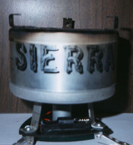
The main difference in the Conover design and mine, is in the base, or blower unit. I found the base unit as it came from the factory to be a little, shall we say, insubstantial. The fan and burner supports rest on a 4"x4" aluminum plate that has the four corners turned down to serve as "feet". It is my view that this footprint is too small to provide stable support, and by having four "feet", the stove is all but certain to wobble.
A lesson I learned somewhere a long time ago is that stable designs are based on triangles: a three legged stool will never wobble. When I looked at the base unit of the Zip, I saw a base plate resting at four points, supporting a burner unit at two points, which in turn supports a pot at four points. I won't tell you how many hours I spent trying to devise ways to stabilize this design.
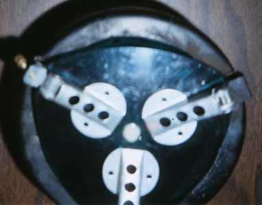
My solution for the base unit is, of course, based on triangles. Three legs support three burner supports, which support the burner unit at three points. At the top of the burner unit there are three, not four, pot supports. This design only reduces the weight of the base unit by half an ounce. But, the modified design makes me much more confident that I won't dump a burner full on hot coals out onto a flammable surface, or ( more importantly ) my dinner onto the ground.
New Legs
The foundation of the new base is a set of three folding legs. Before you think of giving me credit for designing these ingenuous little units, I should tell you that I stole them off my Coleman Peak 1 Apex II stove. When deployed, these babies provide a support radius of about 3-1/2 inches ( which would be a diameter of 7 inches, but you knew that ). One of the legs also has a little adjustment screw that lets you compensate if the stove is resting on uneven ground. I don't know about you, but I feel better already.
These can be ordered directly from Coleman. Their phone number is 1-800-835-3278. The part is called a "Stabilizer Leg Kit", and is part number 450-5161. A set I ordered just arrived today (03/08/1999). The nice lady on the phone said the part would be $6.60, and the box says the shipping was $3.20. ( I'll confirm the charges when my Visa bill comes. )
The legs support both the base plate ( which the fan motor sits on ) and the burner unit supports.
The Base Plate
 The base plate is a piece of Lexan. You may be asking yourself "Where am I going to find a piece of Lexan?", and I was wondering the same thing. But then serendipity happened. I was reading something somewhere on the 'net that mentioned how Lexan dinner plates are unnecessary for us lightweight backpackers, and WHAM! Off I went to my local EMS, where sure enough I found an unnecessary Lexan backpacking plate, which I immediately brought home and sawed into little pieces.
"But why Lexan?" you might ask. Partly I'm just a sucker for space-age materials. But mostly, I wanted to glue the motor and the battery holder to the base plate, to eliminate hold down brackets and bolts and such, and I figured that I'd get better glue adhesiveness on plastic than aluminum.
Hopefully, the schematic will give you enough information to lay out the base unit. I cut it out slightly oversized using a hand-held jig-saw, and finished shaping it on a router table. Each side arc is centered at the opposite bolt hole. The hole in the center is 11/32", the three bolt holes are 3/16"
The Burner Unit Supports
For the burner unit supports though, I fell back to aluminum. I don't know how to bend Lexan, and these guys are going to get a little hot at the top end. Again the issue of a source for the raw materials had me stumped for a while. Home Depot didn't seem to have what I was looking for. Then, out of the blue, I remembered an aluminum yard-stick (actually, I think it was a meter-stick) that I hadn't used in years propped up in the corner of my home office. Its about 1/16" thick, which seems about perfect.
To start, I cut three pieces of aluminum about 1/2" wide and 2-1/2" long. By the way, I'm primarily a woodworker, but someone told me long ago that any tool that will cut wood will cut aluminum without causing damage or undue dulling. I can't say that I know this is true, but I've been operating on the premise that it is.
Using a utility knife, I scribed lines across the burner support pieces the following distances from what will be the bottom end: 1/2"; 2-1/8; 2-1/4. These lines are where bends will be made, but don't do that yet! There's more machining that needs to be done, that will be much easier to do while the pieces are still flat.
A cut needs to be made in each unit. It's parallel to the long side, centered, starts at the top, and continues for 3/8", which not coincidentally, will bring it exactly to one of the lines scribed in the previous step.
Next holes for the bolts need to be drilled. These are centered in the 1/2" by 1/2" area at the bottom of the support units. You can eye-ball this, or measure and scribe reference lines.
Lastly, one of the support units needs to be modified to accommodate the switch. The cut-out for the slide part needs to be 1/4" wide and 1/2" long. I made the cut out by first drilling several 1/4" holes, and then removing the rest of the material with a file.
The cut-out should be centered side-to-side on the unit. You may want to judge for yourself how high or low you want the switch to be on the support unit. The first time I did it, I centered the cut-out on the 1-3/4" vertical section of the unit. This turned out to be too high, as the fan would not quite clear the top of the switch-box. Perhaps overreacting, I tried again, moving the switch as low on the unit as it could go. This put the top of the cut-out about 1-1/4" from the bottom end of the piece (3/4" above the first bend). If you go this low, you'll have to snip off the lower screw flange, and rely on just one screw to hold the switch in place (more weight saved!).
Once you've got the cut-out for the slide where you want it, locate the position of the screw hole(s) by using the original battery/switch case as a template.
Now, the burner unit supports are ready to be bent. My technique for making the bends involved a propane torch, a pair of leather gloves, and a large pair of Vice-Grip pliers. I could bend the aluminum without heating it, but I found this made the piece rather brittle, and likely to break under stress.
Each piece requires three bends. Make the bottom-end bend a little less than 90 degrees, and the top-end bends a little more than 90 degrees. Small adjustments can easily be made later. Hopefully, the pictures will allow you to figure out what the pieces should look like when they're done, because I'd have a hard time describing it.
Blower Unit Assembly
You're almost ready to assemble the base unit, but there are a few things you need to find before you can continue.
First, the little machine screws that come with the Coleman stabilizer legs are too short to work here. I happened to have some longer ones in my workshop, which saved me a trip to Home Depot.
Second, in order to disassemble the original Zip base unit, you have to remove the fan from the motor. It may not be obvious, but the fan is held on by a teeny-tiny set screw, for which you need a teeny-tiny Allen wrench. The smallest Allen wrench in my set happened to fit. I don't think I've ever used it before.
Third, you need a battery holder. I debated the merits of AAA vs AA batteries, and eventually settled on the latter. Actually, once I realized that an Lithium AA battery weighs the same as an Alkaline AAA battery (3/8 oz), but has 5 times the power, the choice was easy. You can get little plastic battery holders at Radio Shack. The one that holds a single AA battery is item #270-401a.
 Now, you're finally ready to assemble the base unit. Put the machine screws through the holes in the the support units and the base plate and screw the legs onto the ends of the bolts. Then try to tighten the screws while keeping everything properly aligned. This seems to require three hands to do. I put the burner support unit with the cutout for the switch on the same corner as the stabilizer leg with the adjustment screw on it. This just provides a visual clue to where the switch is.
The three burner support units should lean toward the center to the point where their outer circumference at the top of their vertical sections is slightly larger than the circumference of the large hole in the bottom of the burner unit. To state this another way: when the three support units are clipped into place, they should have just a slight outward tension. Just enough to keep things snugly in place.
Since the Lexan base plate is pretty flexible, you may have to disassemble the base unit to make the adjustments to the bottom bends, which is a pain. But, a couple of tries should be enough to get them properly adjusted. Once you're satisfied with the angle of the lower bends, adjust the bends of each units upper "tongues". The lower "tongue" should be parallel to the base plate, the upper can tip just slightly up from that, which will make it easier to engage the bottom of the burner unit. It may be necessary to use a file to smooth some of the rough edges of the "tongues". When you've got this right, it should be easy to assemble and disassemble the two halves of the stove, and when assembled, the burner unit should rest flatly on the lower "tongues" of the three burner support units.
Note that when you squeeze the tops of the burner support units together when assembling and disassembling, it's the Lexan base plate that does most of the flexing, not the support units. If the support units were doing the flexing, I'd be worried about metal fatigue, so I figure this is a good thing.
Now that the burner supports are all set, you can assemble the rest of the base unit. This involves gluing the motor and the battery holder to the base plate. I used an epoxy glue for this, and it seems to be holding well. When positioning the motor, the only thing worry about is the orientation of the wiring leads. I'll leave it up to you to figure out what you want here. The battery holder will just fit between two of the burner supports, so it's best to have them in place when you do the gluing. I put the battery holder pretty close to the motor. If I had it to do over again, I'd move it closer to the outer edge. I think the batter would be easier to get in and out that way.
Once the glue has cured, the last remaining task for the base is the wiring. I'm not very good at soldering, but I figured even a mediocre soldering job would be better than the little wire-nuts that came with the stove, so I soldered all of the wiring joints. I'll assume that you can figure out the circuitry on this.
The Burner Unit
For the burner unit, I mostly followed the Conover/John O design. I replaced the double walled steel burner bowl with the single walled titanium bowl, using the Evernew titanium Sierra Cup. But, while I trimmed off the part of the handle that sticks out from the cup, I left the part that goes around the rim. This was mostly due to concerns about structural stability. I reused the original pot supports, but I reduced their number from four to three.
To hold the burner bowl in place, I drilled holes in the Sierra Cup at 120 degree intervals, and attached the pot support units using small bolts, nuts, and lock-washers that (again) I had hanging around in my shop. The bolts are 1/8" diameter by 3/8" long (or something very close to that).
The new burner bowl needs to have some holes, of course. My original bowl had 16 holes in it, and the directions for the Conover/John O unit also specified 16 holes, but I decided to be cautious. I want the stove to maintain a nice simmer at low fan speed, and I was afraid that too many holes might mean too hot a fire. I started with 8 holes, but that didn't seem to be enough to get a really hot fire cooking with the fan at the the high setting. So, I increased it to 12 holes. For now, this seems to provide a good balance. I can always drill more holes later.
Finally ( I think it's finally ) you can further reduce the weight and volume of the stove by reducing the height of the burner unit. Unfortunately, I didn't write down how much I trimmed off the top of the outer cylinder, but the final height of the unit ( not including the pot supports ) is 3 inches. I'm guessing that more could be trimmed without adversely affecting the performance of the stove, but that's just a guess. Before you snip, it's probably a good idea to mark out new locations for the three little bumps in the outer cylinder, that correspond to three little bumps in the upper ring, that help hold the unit together. Actually, I couldn't figure out how to make new bumps that looked like the original bumps, so I drilled three little holes instead. The holes seem to hold the unit together ever more firmly than the bumps did.
Packing it up
It may have occurred to you to wonder whether the totally redesigned blower unit would now nest in the totally redesigned burner bowl. The answer, I'm happy to say, is yes it will! Just a slight downward pressure, and then a bit of a twist to engage the three corners of the base plate under the three pot supports, and you're all set.

Statistics
The blower unit, without a battery, weighs 4 oz ( my kitchen scale weighs to the nearest 1/8 oz ). That a reduction of a whopping 1/2 oz from the original blower unit & batter/switch box assembly. But you've also gained considerable stability by using the adjustable Coleman legs. The legs, by the way, weigh 1 oz.
The burner unit now weighs 6-5/8 oz. That's down from 13 oz out of the box. If you're looking for the most weight reduction for the least amount of work, and don't care whether or not you've got the coolest looking modified Zip Stove on the trail, you could forget about all of the blower unit modifications, and just do the burner unit. The original blower unit will nest in the redesigned burner unit.
So, that's a total weight of 10-5/8 oz without a battery, or 11 oz with a lithium AA battery.
Good Luck & Happy Trails.
Peter
pnyberg@pipeline.com